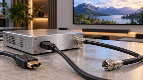
A single HDMI cable works well when a source and a screen sit close together. The challenge changes when the same picture must reach televisions across a hotel, classrooms throughout a school, or displays on several floors of an office building. Long distances, multiple destinations, and existing infrastructure make ordinary HDMI connections difficult to scale. HDMI over coax offers a way to carry content from an HDMI source through coaxial cabling. Depending on the equipment, it can extend a connection between two locations or turn the source into a television channel distributed to many screens. Understanding the difference is essential. This article explains how these systems work, where they fit, and which technical details determine whether an installation delivers reliable pictures and sound.
1. What HDMI Over Coax Actually Means
HDMI over coax describes a category of solutions rather than one universal transmission standard. An HDMI source cannot normally connect directly to a television’s antenna input through a passive cable adapter. The interfaces carry different signals and require active electronics to perform the necessary conversion.
One approach uses a transmitter and a matching receiver. The transmitter converts the incoming HDMI signal into a format suitable for coaxial transport, while the receiver reconstructs an HDMI output at the display. Transport methods, supported features, and compatibility vary between manufacturers and product families.
Another approach uses an encoder and RF modulator. This equipment compresses the incoming video, packages it into a broadcast transport stream, and places it on an RF television channel. Compatible televisions receive the service through their tuners.
2. Extending One Connection or Serving Many Screens
A dedicated extender is useful when the objective is to connect a source to a remote display while retaining an HDMI connection at the receiving end. Depending on the design, it may also support functions such as infrared control or other auxiliary signals.
RF modulation is especially useful for distributing shared content to many televisions. A signage player, camera system, or presentation computer can become a channel within a building’s television lineup. Viewers select that channel using their television remote, provided the tuner and decoder support the transmitted service.
The infrastructure requirements differ. A broadcast RF network can distribute channels through correctly specified splitters, taps, and amplifiers. A proprietary extender may require a dedicated cable path and may not operate through ordinary television distribution components. Never assume that equipment sharing a coaxial connector can coexist or interoperate. Check the manufacturer’s topology requirements before reusing an existing network.
3. Inside an HDMI Encoder and Modulator
An RF distribution system begins by receiving HDMI video and audio. The encoder processes these signals and compresses the video using the supported codec, which may be MPEG-2, H.264, or HEVC. The choice depends on the device and intended receivers, rather than on the HDMI connector itself.
The compressed video and audio are assembled into a transport stream with timing information and program identification tables. A modulator then converts that digital stream into an RF signal following a specified television standard. Examples include DVB-C, DVB-T, ATSC terrestrial modulation, and North American cable QAM implementations.
The television reverses these stages: its tuner selects the carrier, its demodulator recovers digital data, and its decoder reconstructs the program. Consequently, successful reception requires compatibility across the entire chain. A television that supports a particular video codec through an application may still reject that codec through its broadcast tuner, or fail to receive an unsupported modulation standard.
4. Picture Quality, Resolution, and Latency
The presence of an HDMI input does not guarantee that every HDMI source format will be preserved. A device may accept selected input resolutions while encoding a lower output resolution. Verify both input acceptance and the transmitted output, including frame rate, scan format, color handling, and any scaling behavior.
Compression also affects the picture. Fast movement, foliage, fine textures, and rapidly changing scenes can reveal artifacts when the encoder has insufficient bitrate. Presentation slides and signage introduce different challenges: small lettering and sharp edges may suffer from scaling or chroma subsampling.
Latency depends on the complete architecture. Encoding, buffering, transport processing, and receiver decoding can introduce delay in RF systems. Some extender designs also process or compress video. Avoid treating “HDMI over coax” as a promise of negligible latency. Measure the complete path when live interaction, gaming, or synchronization with a separate audio system matters.
5. Receiver Compatibility Comes First
For RF distribution, confirm the tuner standard supported by every display group. DVB-C support does not automatically imply compatibility with a North American QAM configuration, and an ATSC tuner does not automatically support every cable service.
Video decoding deserves a separate check. H.264 and HEVC support depends on profiles, levels, bit depth, resolution, and frame rate. Audio support is equally important: a television may discover a channel and display video while remaining silent because the encoded audio format is unsupported.
A pilot installation should therefore use representative receivers rather than only the newest television available. Test channel scanning, service naming, picture stability, sound, and recovery after a restart. Where built in tuners are unsuitable, external receivers may provide a solution, although they add hardware, power requirements, and another device that staff must configure and maintain.
6. EDID, HDCP, and Audio Handling
HDMI involves negotiation as well as video transmission. Extended Display Identification Data, or EDID, tells a source which formats the connected device accepts. An encoder or extender may present its own EDID, copy a display’s information, or provide configurable settings. Incorrect negotiation can produce an unsupported resolution, missing sound, or an unstable connection.
High bandwidth Digital Content Protection, or HDCP, introduces another compatibility requirement. Protected sources require an appropriately supported and authorized signal path. Many RF encoders are intended for unencrypted HDMI sources. An HDMI socket alone does not establish support for protected content, and changing cables does not resolve a protection mismatch.
Audio must also match the equipment’s capabilities. Some devices accept stereo PCM but cannot process particular compressed surround formats. Others encode audio into a broadcast format for downstream receivers. Confirm input and output formats separately, then check synchronization at the display. Local loudspeakers fed directly from the source may need delay adjustment.
7. Making Existing Coax Work Reliably
Existing coaxial cabling can reduce installation work, but its condition matters. Television distribution normally uses 75 ohm components. Cable type, length, shielding, connectors, and operating frequency determine attenuation and resistance to interference. Poor terminations, damaged cable, and unsuitable adapters can undermine otherwise capable equipment.
Every splitter introduces loss, while taps distribute different signal levels according to their design. Amplifiers can compensate for attenuation within a properly engineered RF network, but excessive gain may overload downstream equipment. An amplifier does not repair a distorted signal or automatically improve reception simply because the displayed power level increases.
Survey the network before commissioning. Identify cable routes, occupied frequencies, splitters, taps, amplifiers, and outlet levels. Confirm that components pass the intended frequency range and that any existing services remain compatible with the new channel plan. Dedicated extender links require their own checks, since television amplifiers or splitters may not support the extender’s transport method.
8. Planning Channels and Managing the System
RF distribution requires a deliberate frequency plan. Select available carriers that fit the television standard and existing network. Avoid placing a new signal on an occupied carrier. A service’s displayed channel number is not necessarily the same as its physical RF frequency, so document both tuning parameters and viewer facing identifiers.
When several services share a multiplex, capacity planning must include video, audio, signaling, and transport overhead. Average video bitrate alone is insufficient if simultaneous peaks can exceed available capacity. Encoding settings and multiplex behavior should be chosen together, with representative content used during validation.
Operational details also influence reliability. Equipment needs suitable ventilation, stable power, accessible management, and saved configuration backups. For important installations, evaluate redundancy and recovery procedures. A successful system should remain understandable to the people responsible for running it after the initial installer has left.
9. Testing, Troubleshooting, and Choosing Wisely
Commission the system in stages. Begin with a short, known good HDMI connection and confirm that the encoder or transmitter receives stable video and audio. Next, test a nearby receiver before connecting the complete distribution network. This sequence separates source compatibility problems from transport and cabling faults.
For RF systems, measure signal level, Modulation Error Ratio, and relevant Bit Error Ratio indicators at representative outlets. If every service on a carrier fails, investigate shared RF or transport conditions. If one service fails, examine its encoding parameters, signaling, and source behavior.
HDMI over coax works best when the architecture matches the application. Dedicated extension can suit a remote display, while RF modulation can efficiently deliver shared programming to many televisions. Define the required viewing experience, verify receiver compatibility, and test the actual infrastructure. With those foundations, existing coax can become a dependable platform for modern video distribution.
About the Author